WIP revision of one of the flight boards
Background
In Summer 2022, after a 3-hour road trip from LA to the Mojave desert, we arrived at
the Friends of Amateur(FAR) launch site, 30 miles north of Edwards AFB. After
countless hours of setup overnight, we launched BZB for the 3rd and last time.
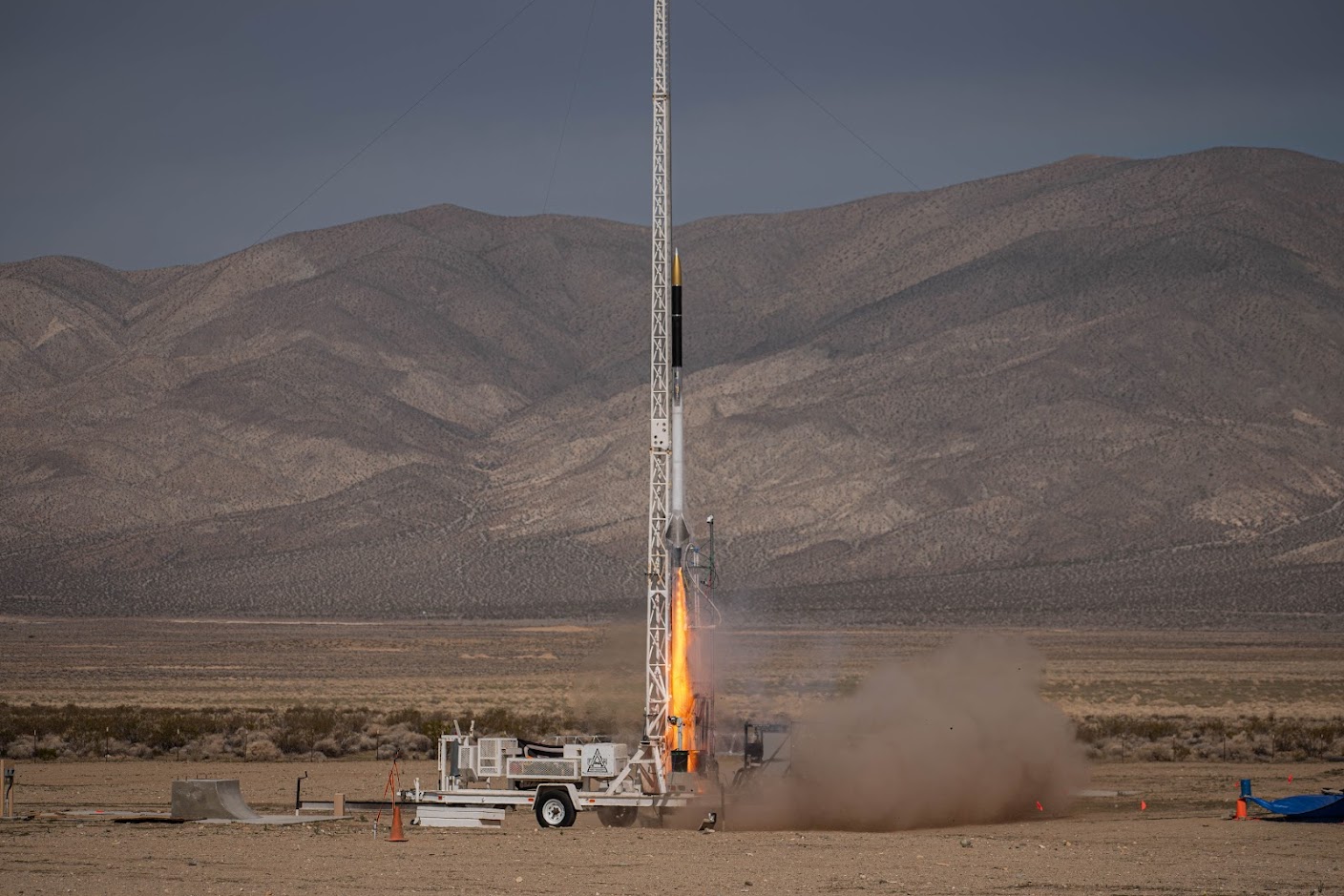 Photo by Andrew LaPrade
BZB is a MethaLOX bipropellant rocket. Built for the FAR-MARS competition by
Purdue Space Program, and designed to reach 35k ft, the project started nearly a
year before I joined the team.
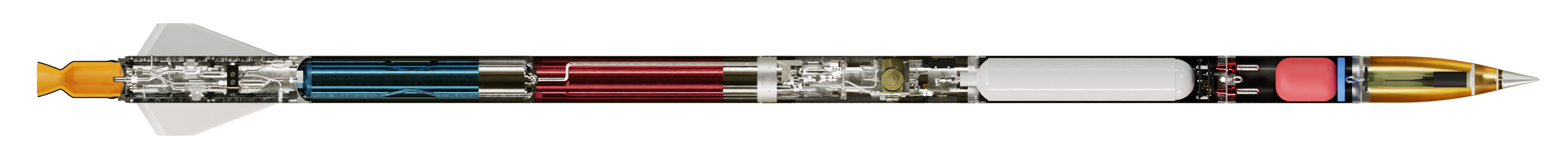
Cutaway render of BZB, me
BZBs avionics got a few improvements after I joined the team, some of which I
contributed to. But the next rocket, CMS, I'd play a much bigger part in.
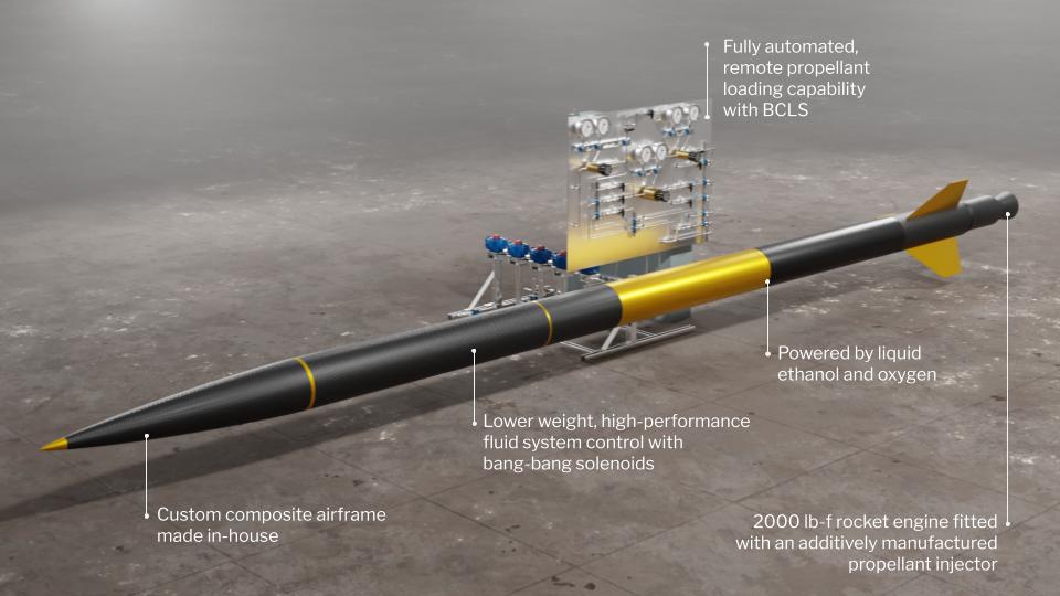
It was decided that this rocket would use a bang-bang tank pressurization
system, where instead of a regulator, solenoid valves would be switched
on and off quickly to flow helium into the fuel tanks. This made Avionics
a critical system of the rocket.
As work on BZB slowed down, Taylor
Duchinski and I got started
working on the avionics for CMS. On his website, you'll find an incredible
amount of detail on the CMS's electronics. The picture of the board above was
designed by him.
As the (other) avionics lead and CS student, I'll be focusing on the system
design, and how we arrived at some of the hardware design choices that we did
for this rocket.
Microcontroller selection
This one's a never-ending tug-of-war between the CS and the ECE. All things
aside, I would've opted for the STM32H7 line of MCUs, or at least something
like an STM32F. STM32s are great, they have all the performance you need,
and a passable SDK and toolchain. Unfortunately, system design on the rocket
occurred around the same time as a massive chip shortage. Stock for these chips
was uncertain, and we knew we were going to fry more than a few.
With these factors considered, we opted for the RP2040, by the Raspberry Pi
Foundation. Rocking two ARM Cortex M0+ cores and 264K of SRAM, this chip was a
beast by no means. But for our purposes, it was sufficient, cheap, and very much
in stock.
One of my most emphasized factors for MCU selection was how easy it was to
program. With Arduino's at a 10 and whatever NXP is doing at a 1, RP2040 scored
a firm 11.
The SDK for this chip was a single Git repo, and the entire build process could
be managed with a short CMake script.
I mean, just look at this (from the SDK
docs)
cmake_minimum_required(VERSION 3.13)

# initialize the SDK based on PICO_SDK_PATH
# note: this must happen before project()
include(pico_sdk_import.cmake)

project(my_project)

# initialize the Raspberry Pi Pico SDK
pico_sdk_init()

add_executable(hello_world
    hello_world.c
)

# Add pico_stdlib library which aggregates commonly used features
target_link_libraries(hello_world pico_stdlib)

# create map/bin/hex/uf2 file in addition to ELF.
pico_add_extra_outputs(hello_world)
To top it off, these chips were impossible to brick. I mean it. These
chips come with a permanent bootloader ROM activated with an input pin, so no
matter how much you mess up the firmware, you can always flash it again over USB.
ADC selection
Honestly, my only constraint was that it communicated over SPI. I2C sucks. We
settled on the ADS131M02. It
- Sampled up to 32ksps
- Used SPI
- Didn't multiplex inputs
- Delta Sigma sampling
And this is all we were looking for in an ADC.
Why I2C sucks
My hatred for I2C was born after working with the BNO055, a cheap IMU that's
commonly found in older smartphones and model rockets that land themselves.
While writing a driver for this chip, I discovered the lovely fact that I2C has
a "feature" called clock stretching, where if a peripheral device needs the host
to wait, it can pull the SCK line low until it's done.
This excuse of a feature caused me several unnecessary hours of frustrating
debugging, after which I vowed to never work with an I2C device again. And so
far I haven't.
Inter-board communication
After much deliberation, we decided that the rocket is to have 3 computers (not
for redundancy).
These are as follows
- Engine Modulation Unit (EMU) - closed loop tank pressurization, pyro ignition,
launch countdown
- Lower Flight Computer (LFC) - all non-critical sensors in the fin can
- Upper Flight Computer (UFC) - all non-critical sensors in the mid-airframe, an
IMU (inertial measurement unit), telemetry radio, LTE modem
The reasoning for keeping upper and lower flight computers is simple, the
sensors they need to sample are in different parts of the rocket, and we'd
prefer to keep analog wires short.
EMU is a separate board because it's flight critical, and it's the minimum
amount of hardware needed to fly.
With these computers, we need these lines of communication:
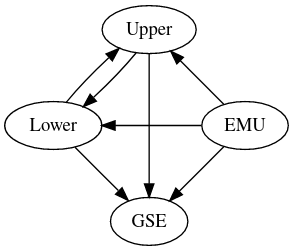
All computers need to store all data (for redundancy). UFC needs data from LFC
and EMU to transmit. GSE needs data from all three, for launch operators to view
while the rocket is on the pad.
Our options were as follows
SPI was very quickly dismissed, because even the thought of routing
voltage-mode, single-ended, physical specification-less wires across the length
of the rocket is the stuff of nightmares.
CANBUS didn't have the bandwidth we needed.
During one of our workdays, I jokingly suggested that we use Ethernet across the rocket, and right after I said that, I realized we found the solution. Ethernet is going to be our mode of communication between the boards on the rocket, and to the ground.
It's perfect, it ticks all the boxes
- Physical spec
- Cheap, proven, off-the-shelf hardware
- All the bandwidth we need
Just one problem - RP2040 doesn't have an Ethernet MAC. But this wasn't a problem at all because, as it turns out, there exists a market for SPI to Ethernet chips, and WizNet happens to make one called the W5500. This, with an off the shelf switch was enough for all our communication needs.
Of course, Taylor's attempts at a physical implementation weren't without hitches, but no problem was encountered which wasn't fixed by throwing multiple transformers at the problem (joking, only one transformer needed to be thrown).
Radio
Oh boy, where do I even begin? At the solution - the RFD900.
It's a 1W 900MHz (the unlicensed ISM band) radio, with an LOS range that can
reach 60 km in some scenarios. We only needed 25.
Arriving at this wasn't easy, and I wasn't set on the decision until an industry
expert vouched for its effectiveness.
I spent an unreasonable amount of time looking at sample implementations for
chips like the TI CC1101, and shopping for >1W amplifiers that we could
(presumably?) use with a HAM license.
The antenna design was also a whole can of worms. At some point, we were designing
for the mid-airframe panels to be carbon fiber, a conductive material that
severely impedes radio. We explored the use of getting PTFE copper-clad, etching
a patch antenna on it, and heat-forming around the circumference of the vehicle.
This wasn't our idea, we got it from this
paper, which contains this very
promising sentence: "Destroy by any means possible to prevent disclosure of
contents or reconstruction of the document. Do not return to the originator.", followed by "UNCLASSIFIED".
In the end, we decided it would be too impractical to do anything other than just change the mid-airframe panels to be E-glass, a class of fiberglass transparent to radio, and use an off-the-shelf monopole antenna.
We also added LTE to the rocket, because we found that our launch side had reception when we were launching BZB.
System Design
Combining all of this, we arrive at
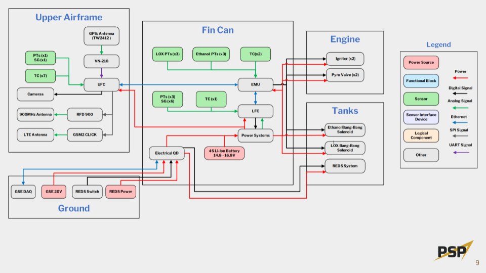 From our preliminary design review slides, some details are outdated
The full PDR can be seen here